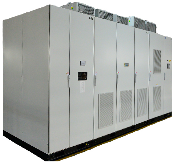
The high voltage inverter is an AC-DC-AC voltage source inverter with multi-unit series structure. It realizes sinusoidal waveform of input, output voltage and current through multiple superposition technology, effectively controls harmonics, and reduces pollution to power grid and load. At the same time, it has complete protection devices and measures to protect the frequency converter and load, in order to eliminate and avoid losses caused by various complex conditions, and create greater benefits for users.
2. Protection of high voltage inverter
2.1 Incoming line protection of high voltage inverter
Incoming line protection is the protection of the user’s incoming line end and frequency converter, including lightning protection, grounding protection, phase loss protection, reverse phase protection, unbalance protection, overvoltage protection, transformer protection and so on. These protection devices are generally installed in the input end of the inverter, before running the inverter must first ensure that there is no problem in the line protection before running.
2.1.1 Lightning protection is the type of lightning protection through the arrester installed in the bypass cabinet or the input end of the inverter. The arrester is an electrical device that can release lightning or release the overvoltage energy of the power system operation, protect the electrical equipment from the harm of instantaneous overvoltage, and cut off the continuous current to avoid the system grounding short circuit. The arrester is connected between the input line of the inverter and the ground, and is connected in parallel with the protected inverter. When the overvoltage value reaches the specified operating voltage, the arrester immediately acts, flows through the charge, limits the overvoltage amplitude, and protects the equipment insulation; After the voltage is normal, the arrester quickly restores to its original state to ensure the normal operation of the system and prevent damage due to lightning strikes.
2.1.2 Ground protection is to install a zero-sequence transformer device at the inlet end of the inverter. The principle of zero-sequence current protection is based on Kirchhoff’s current law, and the algebraic sum of the complex current flowing into any node of the circuit is equal to zero. When the line and the electrical equipment are normal, the vector sum of the current in each phase is equal to zero, so the secondary winding of the zero-sequence current transformer has no signal output, and the actuator does not operate. When a certain ground fault occurs, the vector sum of each phase current is not zero, and the fault current generates magnetic flux in the ring core of the zero-sequence current transformer, and the secondary voltage induction of the zero-sequence current transformer is fed back to the main monitoring box, and then the protection command is issued to achieve the purpose of grounding fault protection.
2.1.3 Lack of phase, reverse phase, unbalance protection, overvoltage protection. Lack of phase, reverse phase, unbalance degree protection, overvoltage protection is mainly by the inverter input voltage feedback version or voltage transformer for line voltage acquisition, and then through the CPU board to determine whether it is a lack of phase, reverse phase, input voltage balance, whether it is overvoltage, because if the input phase, or reverse phase, and voltage imbalance or overvoltage is easy to cause the transformer to burn. Or the power unit is damaged, or the motor is reversed.
2.1.4 Transformer protection. The high voltage inverter is only composed of three parts: Transformer cabinet, power unit cabinet, control cabinet composition, transformer is the use of tangential dry type transformer to convert high-voltage alternating current into a series of different angles of low voltage power supply for the power unit, the transformer can only be cooled by air cooling, so the protection of the transformer is mainly through the transformer temperature protection, to prevent the transformer temperature is too high, and cause the transformer coil burned. The temperature probe is placed in the three-phase coil of the transformer, and the other end of the temperature probe is connected to the temperature control device. The temperature control device can set the automatic start temperature of the fan at the bottom of the transformer, the alarm temperature, and the trip temperature. At the same time, the temperature of each phase coil is displayed several times. The alarm information will be displayed in the user interface, and the PLC will alarm or trip protection.
2.2 High voltage inverter outlet side protection
The output line protection of high voltage inverter is the protection of the output side of the inverter and the load, including output overvoltage protection, output overcurrent protection, output short circuit protection, motor overtemperature protection and so on.
2.2.1 Output Overvoltage protection. The output overvoltage protection collects the output voltage through the voltage sampling board on the output side. If the output voltage is too high, the system will automatically alarm.
2.2.2 Output Overcurrent Protection. Output overcurrent protection detects the output current collected by Hall and compares it to determine whether it causes overcurrent.
2.2.3 Output Short-circuit Protection. The protective measures for the short circuit fault between the stator windings and the lead wires of the motor. If the inverter determines that the output is short circuit, it immediately blocks the power unit and stops running.
Post time: Jul-28-2023

